By Enrico Poli, Application Engineering Manager, STMicroelectronics & Prospero Lombardi, Application Engineer, STMicroelectronics
The demand for high-power motor drive solutions has been on the rise in recent years. In particular, low-voltage servo driving applications are pushing for reliable systems able to manage a significant power transfer to the electric motor, ranging from a few hundred to thousands of watts. This application field is dominated by 3-phase brushless motors, thanks to their flexibility and strong performance in positioning and regulating the torque applied to the mechanical load.[1]
Since these applications commonly use standard industrial voltages such as 24V and 48V, their power stages must manage currents of several tens of amperes, leading to a critical design from different perspectives. Furthermore, this design complexity is also exacerbated by the latest market trends pushing for very compact motor drivers to be mounted on top of the same controlled motor, with the advantage of reduced cabling, radiative emissions, and cost. In this regard, the sizing of final transistors composing the power stage and their connection to the servo motor are crucial because the significant current levels may increase power losses and temperatures, as well as overstress board traces that must be properly addressed.[2]
To get the most out of 3-phase brushless motors, advanced control techniques are needed, such as the Field Oriented Control (FOC), where the magnetic field produced by currents flowing into motor windings is dynamically updated to maximise the efficiency of the electrical machine.
An example of this is the STSPIN32G4 from STMicroelectronics, which combines a high-performance STM32 microcontroller with a triple half-bridge gate driver and flexible power management circuitry. While the microcontroller manages most advanced motor control algorithms, the driver fully controls the power stage. The new EVLSERVO1 reference design (Figure 1) uses STSPIN32G4 to target servo drive applications.
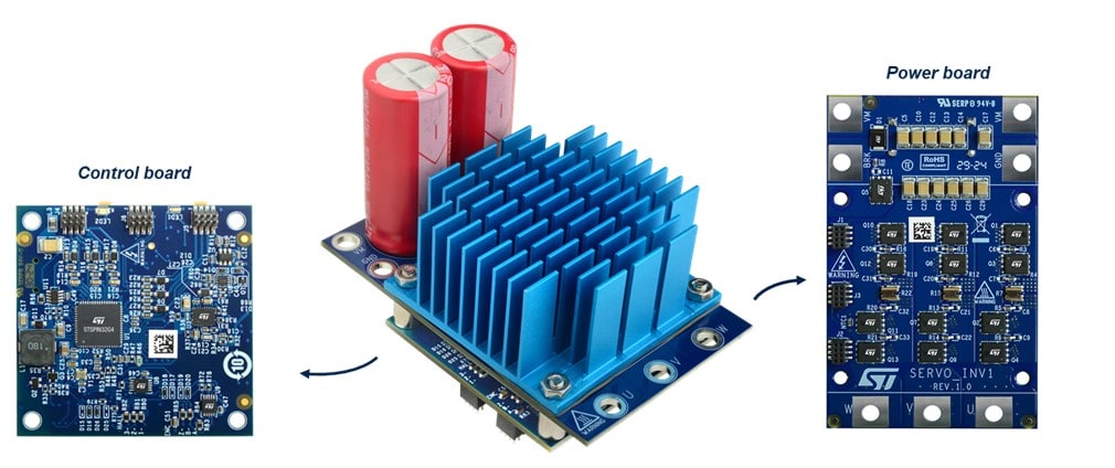
Figure 1: EVLSERVO1 reference design. (Source: STMircroelectronics)
Design Description
The EVLSERVO1 is based on a modular design, as visible in Figure 1, consisting of two printed circuit boards (PCBs) stacked together: the control and the power board. The design targets a 3-phase brushless DC motor with continuous operating power of up to 2kW with passive cooling or 3kW using a fan. The system is intended to operate in industrial environments using a nominal bus voltage of up to 48V. However, it has been designed with a large margin, extending its operative voltage to 75V. The maximum output current to the motor is 63Arms or 42Arms, respectively, with or without fan.
Power board
Figure 2 shows the power board that mainly consists of 12 STL160N10F8 MOSFETs arranged in a triple half-bridge configuration. Each switch for the low-side and high-side sections is made of two parallel transistors. The system protects against overvoltage on the bus during regenerative braking. This is a key feature because when the servo driver is requested to reduce operating speed, the control algorithm adjusts the modulation applied to the motor to reverse the power transfer.
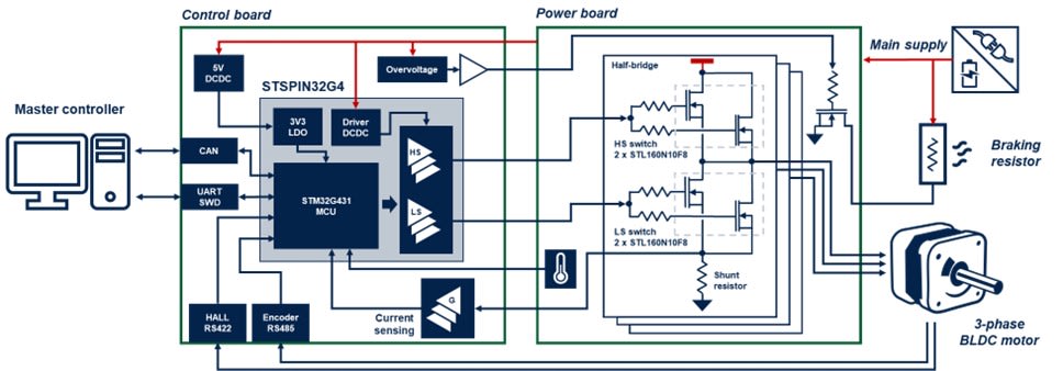
Figure 2: EVLSERVO1 block diagram and connections. (Source: STMircroelectronics)
Control board
The STSPIN32G4 is the core of the control board, as illustrated in Figure 2. The device executes the control algorithm on the embedded high-performance STM32G431 microcontroller, featuring a Cortex®-M4 core and running with a clock frequency of up to 170MHz.
The system provides bidirectional sensing of motor currents as required by the FOC control. The sensing is performed via the drop voltage on the three shunt resistors, one for each motor phase, that is amplified by a gain stage based on operational amplifiers. The amplified signals are then sampled and converted by two 12-bit ADCs within STSPIN32G4.[3]
Performance
To verify the robustness and performance of the EVLSERVO1, the setup shown in Figure 3 was used.
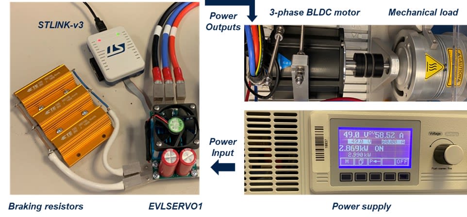
Figure 3: EVLSERVO1 driving high power load. (Source: STMircroelectronics)
The system’s main input was connected to one DC power supply able to source electric power up to 3.5kW. In contrast, the three outputs were connected to a 3-phase BLDC motor that can deliver a mechanical power of 4.47kW (6HP) when rotating at 3000rpm. The mechanical power from the motor was dissipated via a hysteresis brake, while the motor was coupled with a flexible joint. Three power resistors were connected in parallel as braking resistors with an overall resistance of roughly 0.9Ω, considering the wiring to the board.
The STSPIN32G4 was configured with firmware implementing the FOC control algorithm. The EVLSERVO1 was pushed to its maximum operating limits, managing an average power close to 3kW, as seen on the power supply display in Figure 3.
The system reached a steady state condition after roughly 15 minutes of working in an environment at about 25°C. The hottest point on the board was a low-side MOSFET that reached a temperature of 113°C, as visible on the left side of Figure 4. After this test, the fan was turned on, and the output current increased to 63Arms. In this condition, the maximum temperature of the hottest MOSFET decreased to 105°C, as visible on the right side of Figure 4.
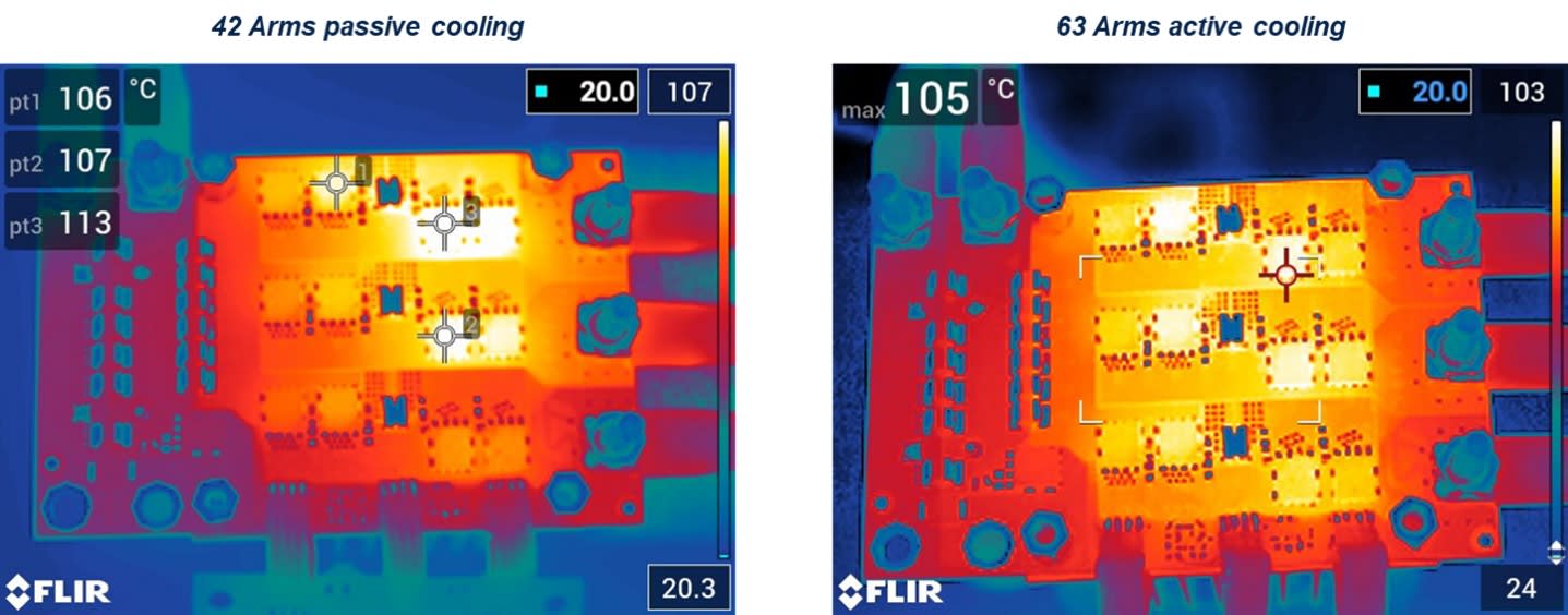
Figure 4: Thermal imaging of EVLSERVO1 power board. (Source: STMircroelectronics)
Figure 5 shows an example of an intervention for the braking resistor. In this case, the mechanical brake was disabled to avoid the dissipation of significant power, except for friction losses. In contrast, the mechanical inertia of the setup was exploited to store energy during the rotation, with the motor running clockwise. Then the drive was commanded to suddenly revert the shaft rotation counterclockwise in order to stimulate regenerative braking. As can be seen in the figure, there was an initial phase where the bus voltage increased since the motor behaved as a generator and a certain current was injected into the bulk capacitors of the system.
During the entire braking phase, the resistors were activated multiple times in pulsed mode, resulting in the bus voltage being clamped in a safe range between 62V and 65V. In this braking test, the pulsed current reached 60A, leading to a peak power of roughly 3.4kW and an average power of 148W. During the braking phase, the EVLSERVO1 provided an average power of around 4.7W to charge bulk capacitors inside the equipment. Then, the motor reverted its direction and started accelerating counterclockwise with power from the supply that progressively increased up to 400W to reach the target speed.
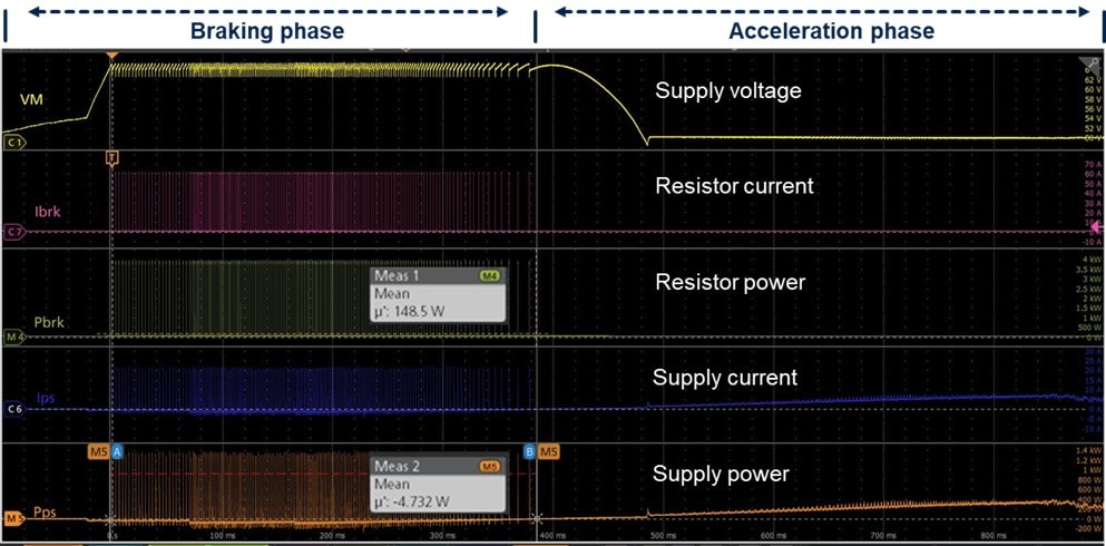
Figure 5: Intervention of braking resistor. (Source: STMircroelectronics)
Conclusion
Low-voltage servo driving applications demand reliable and effective motor control systems. The reduced form factor EVLSERVO1 allows the electronics to be located close to the motor, which is desirable in servo drive applications. Several protections are available, including dedicated circuitry to manage possible bus overvoltage due to regenerative braking for a robust design under fault conditions.
Sources
[1] https://ieeexplore.ieee.org/document/6713062
[2] https://www.st.com/resource/en/technical_article/ta0361-thermally-aware-highpower-inverter-board-for-batterypowered-applications--stmicroelectronics.pdf
[3] https://www.st.com/resource/en/application_note/an5397-current-sensing-in-motion-control-applications-stmicroelectronics.pdf